This is a work in progress. Someone with Linux and Raspberry Pi skills can use this info as is, others might want to wait. I’ll try to update this with more “meat” in the setup section. Screenshots, command line entries and all that jazz.
Almost a decade ago I created a cheap SIP pager using a Raspberry Pi. We had just moved the phone system at my previous employer to an Asterisk based SIP VOIP PBX.The old analog pager for their warehouse was already on its last legs, and the employer did not want to pay the outrageous fee companies were charging for SIP pagers.
I had a few Raspberry Pi laying around and was looking for an interesting project for them, so I created a SIP paging system using the Raspberry Pi and PJSAU, a PSIP based SIP client that can be run from the command line. It wasn’t perfect, the sound was fairly weak, and it was far from pretty, but it worked.
Now, my current employer wants something similar for our new warehouse. We could purchase some overpriced SIP horns from Algo, CyberData or Valcom. But, knowing how easy it was to create my own and having several Raspberry Pi 4 laying around, I decided to try to upgrade the old design.

Links on the right are to actual parts that were used. None of these are sponsored links. I am simply providing the links as in case you are trying to find what was used for the project.
| Part | Price |
| Raspberry Pi 4 2GB | $ 58.00 |
| Sandisk Pro Endurance 32GB | $ 23.00 |
| Outdoor Electrical Box with fan and thermostat | $ 51.00 |
| 50W Amplifier | $ 15.00 |
| 12V 1.0A Power Supply | $ 9.99 |
| 12V DC Splitter | $ 6.99 |
| Raspberry Pi active cooling aluminum case | $ 17.75 |
| Raspberry Pi 4 Official Power Supply | $ 13.97 |
| CAT6 Cable, 15 foot | $ 8.49 |
| Power strip, 15 foot | $ 13.00 |
| 5in Paging Horn (2) | $ 48.00 |
| Total | $ 265.19 |
Honestly, I used this because I had it laying around. I had purchased several of them when they came out, before the shortages and the price increases. I needed something small that could deal with the heat of a Texas warehouse, that could run a full installation of Linux, with Ethernet and other ports should I decide to add extra functionality to the system.
I have tested various Micro SD cards in similar devices I have spread around the buildings. Even when actively cooled the devices can get pretty warm and I had several of them fail. This model has been able to deal with the heat very well, so I have been using it for most projects.
My initial idea was to print an external case using my CR-10 v3. Unfortunately, while printing something else I killed the hotend. So, I decided to look into outdoor electrical boxes. I found several of them online that were available very cheaply. Some of them included additional features such as weatherprooof seals, vent holes, fans and thermostats. After comparing the price of one that met the project specifications, I found it cost about the same as printing one and adding the additional features. So, I purchased the following enclosure.
It is sold as an Outdoor Electrical Box on Amazon. There are several identical models sold under different vendor names, so I am not sure who actually makes it.
It is a nice enclosure. It feels very sturdy, and has more than enough room for my project. The only complaint I have about the case is the position of one screw on the mounting plate inside the enclosure. The enclosure includes a 12V fan that sits right on top of the screw. To remove the mounting plate so I could actually mount things to it I had to remove the screw. Which meant removing the fan, which was a huge pain. It would be much better if they sold it would those items preinstalled.
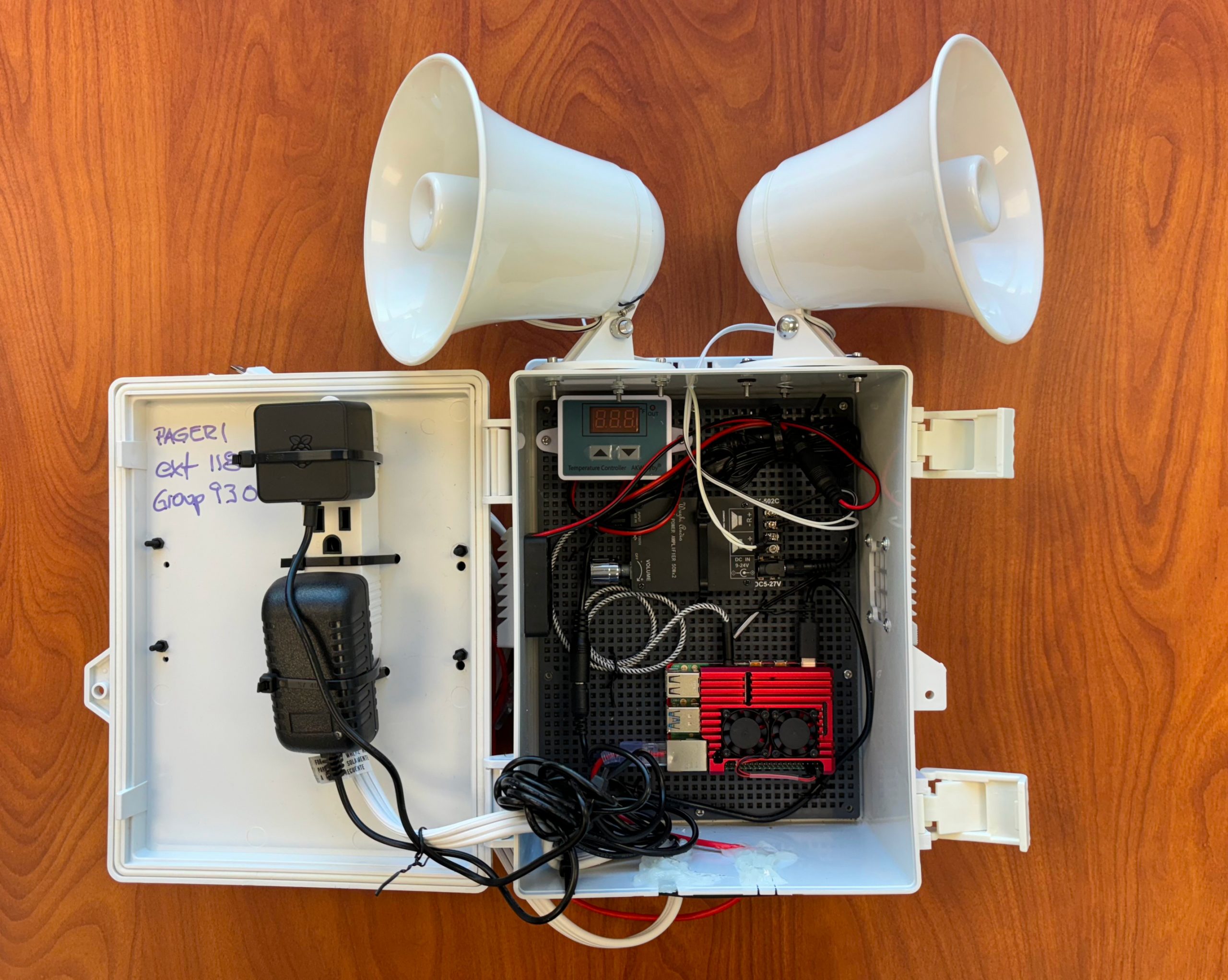
Once I dealt with the mounting plate screw, I was able to easily fit the Raspberry Pi, amplifier, power strip and various cables into the enclosure. I had to zip tie the amplifier to the mounting plate, but was able to screw the Raspberry Pi case directly into the mounting plate. There was enough depth to the case that I was able to mount the power strip to the top. This allowed me to ensure good airflow in the case.
I tested a few different amplifiers. This one was more power than I needed, but it had 3.5mm inputs and was small enough that it would fit the design I had in mind. I almost went with a much smaller amplifier, but it was only 10W and the lack of 3.5mm input made the other one win over. I did test it and it worked perfectly, so if you don’t need something as loud as the one I used, the smaller device would be a good choice.
Only real complaint was mounting. There are no mounting holes on the device. I could have printed something, but it will be inside the enclosure so I simply zip tied it to the mounting plate.
Also, the speaker horns connect using screw in connections. I could have purchased something like this 3.5mm to fork adapter. But, the speaker horn cable was really long and already planned on cutting it. If you are not mounting the speaker horns directly on the box you may consider something like this adapter.
Both the amplifier and the case fan require a 12V DC power supply, and they have 5.5mm x 2.1mm female connectors. Neither of them will use the full amperage of the power supply, so I purchased a DC power cable splitter to reduce the number of devices on the power strip. This power supply was sold by the same company that sold the enclosure, which is the only real reason I chose it.
Even though there is a case fan, I wanted to make sure there was something actively trying to pull the heat from the Raspberry Pi 4. I had this case in a box, unused, so I used it for the project. Seems to work well, in testing the temperature rarely gets higher than 35°C. It screwed on from the bottom, so I was able to screw through the enclosure mounting plate.
I actually had a problem with a cheap off brand Pi 4 power supply before. So, I typically only buy the official power supplies now. Again, had this one lying around in an unopened box.
I really didn’t need a thin CAT6 cable. A standard CAT5 cable would do just fine, since this is not using a lot of bandwidth. I had purchased this from Cable Matters previously and was not using it. Any CAT6 cable would do.
I could have gone with WiFi, but we use Ubiquiti Mesh WiFi in the warehouse. All of the AP are connected via POE cables, no jumping the signal from one to the other. But, I had an issue with a Raspberry Pi 2 Zero on the Mesh WiFi and have been a little concerned about that. There is an available Ethernet port in the ceiling near where this will be mounted. So, I went with Ethernet just to avoid any WiFi issues.
If I had printed the enclosure I was going to use a panel mount power port with two connections on the inside. I couldn’t use that on this box without carving a hole, which I wanted to avoid. So, I simply used a cheap power strip. On the plug side I will probably put a WiFi controllable smart power outlet so I can force a reboot if necessary.
These put out a lot of sound. Not something you would use for playing music, but perfect for overhead paging in a warehouse. A friend of mine swears by this model for usage on his boat. I assume if it can survive on the water it can survive in a hot and humid Texas warehouse. Plus, they are cheap.
These came with 3.5mm plugs, and a long cable. Since I was mounting them directly on the enclosure and the amplifier has simple screw in connections, I simply cut the cables. I screwed them directly into the amplifier.
The hot end on my CR-10 was very customized. Replacing it would require several new purchased. I was looking for an excuse to purchase a Bambu Labs X1C anyway, so this was the perfect excuse.
I wanted a plate for the from of the enclosure. I had used zip ties to mount the power strip to the enclosure door. It left those visible on the front which was a little unsightly. Plus, someone in the warehouse may see the enclosure and not know what it is or what the extension number is. So, I printed a face plate with some useful info that was large enough to be visible from several feet away.
Previously, I used PJSAU as the SIP Client. That is a command line SIP client, part of the PJSIP utility/library. For some reason, I absolutely could not get it installed. It isn’t available in the latest Raspberry Pi OS or Ubuntu distro apt repository. I was able to compile from source, but could not get it to talk to the 3.5mm port. Everything else on the system was able to talk to the 3.5mm audio port. There is no simple method to select the correct port for PJSAU. The problem seems to be ALSA related, and I am sure it is specific to the Raspberry Pi audio implementation. Regardless, after fiddling with it for a week I could not get it to work.
After trying a few other options, I simply went with Linphone. They have a CLI client, but like the PJSAU I could not get it to output audio unless I was logged in at the console. Probably could have gotten it to work but decided I was being stupid. I simply used the GUI client, setup dummy HDMI output and had it start on boot.
Stupid simple to setup. Appears to be reliable. And with everything unnecessary disabled on the system it’s GUI is not really eating up many resources.
This site is primarily for screwing around. There is no need to contact me, but if you insist you can find me on Mastadon at https://mastodon.social/@djinnsour.